
Introduction
When a sensor detects a photon, photoelectrons are released within the pixel (for more information, see our fundamentals page). The number of photoelectrons is measured at the end of exposure and a digital number produced. This is called the analog-to-digital unit (ADU) or the ‘gray level’. However, the number of gray levels does not equate to the number of detected photoelectrons. The most important determining factor of gray levels is the gain of the camera.
For scientific cameras, there is a linear relationship between photoelectrons released and gray levels displayed. The gain is the gradient of this linear response and is expressed in electrons (e–)/gray level (ADU).
For example, if a camera has a gain of 6 e–/gray, then for each 6 photoelectrons of captured signal the displayed value increases by 1 gray level.
The maximum signal that a pixel can contain is also determined by the gain, as well as the bit depth of the camera. For a 16-bit camera, our maximum gray level value is 65,535 – multiplying this (minus any offset value) by the gain provides the available full well capacity – the maximum signal in photoelectrons we can detect.
The offset of a camera refers to the small number of electrons that are within a pixel well before any photons are detected. These determine the black level (i.e. lowest level) of the pixel array. This is to ensure that there are no zero value pixels as no information can be created from a 0 value. As the full well capacity is also a property of the sensor, typically the default gain value for a camera is chosen such that the sensor full well is matched to the maximum displayable signal.
EMCCD cameras differ as they introduce an additional EM gain factor. Through multiplying detected photoelectrons, read noise is overcome even for very low signals, with this multiplication dividing the resulting gain value. Therefore, EMCCDs in low-light imaging modes have very high gain, for example around 0.03 e–/gray.
How to calculate the gain
The system gain can be measured using a mean variance test via the following steps:
- Collect a 100-frame average image (zero-integration dark image) and label the image “bias”.
- Collect two even-illumination images and label them “flat1” and “flat2”. Your experimental setup should be static enough that the images are “identical”, except for camera noise and photon shot noise.
- Calculate a difference image through subtracting one image from the other (preserving negative values): diff = flat2-flat1.
- Calculate the standard deviation of the central 100 x 100 pixels in the difference image.
- Calculate the variance by squaring the standard deviation and dividing by 2 (variance adds per image, so the variance of the difference image is the sum of the variance of flat1 and flat2).
- Calculate a bias-corrected image by subtracting the bias from one of the flat images and label it corr: corr = flat 1 – bias
- Obtain the mean illumination level by calculating the mean of the central 100 x 100 region of the corr image.
- The mean divided by the variance equals the gain: gain = mean/variance
Further Reading
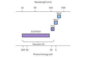
Enhancing UV Sensitivity from 10 – 400 nm
There are many subcategories of UV light, each which need different sensor requirements. These include both physical and chemical sensor changes.
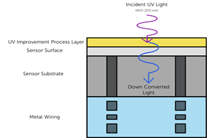
Improving UV Sensitivity Above 200 nm
There are two processes which can be used to enhance UV sensitivity for wavelengths >200 nm: UV photon conversion, and anti-reflection coatings.
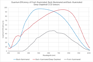
Quantum Efficiency
Quantum efficiency is the percentage of photons that an imaging device can convert into electrons. It is dependent on sensor material and wavelength of light being detected.