
Introduction
Quite often, users of indirect-detection systems assume that the camera manufacturer has carefully selected the ideal combination of sensor, fiberoptic (faceplate/taper) and phosphor to preserve image quality. Unfortunately, each application requires different parameters, and it is difficult for a manufacturer to know every requirement. Therefore, it is imperative that each customer understands the component options available to obtain optimal performance. Although there are many requirements to consider, the main specifications to consider when selecting a fiberoptic are the size of the fibers, the type of extramural absorber (EMA), and blemishes/distortions.
Size of Fibers in a Fiberoptic
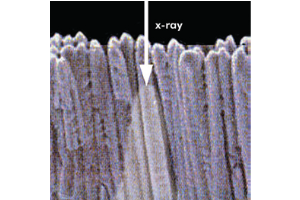
When coupling a fiberoptic to a CCD/CMOS, the ideal size of the fiber will be the same as the pixel size. Unfortunately, it is practically impossible to manufacture a fiberoptic faceplate or taper with a fiber pattern/size that will precisely match the pixel pattern (Fig.1). However, if the fiber size is selected to best match the pixel size, a mismatch will occur (Fig.2) and a huge variation in pixel-to-pixel sensitivity (pixel-to-pixel response nonuniformity, PRNU) will occur, which will be undesirable for almost all applications.
To avoid this situation, it is very important to choose a fiber size that is significantly smaller than the CCD pixel size, so there are many fibers per pixel. For this reason, our camera systems utilize a fiber size that is 3–4 times smaller than the pixel size (or as small as practically possible), so there are at least 9 fibers per pixel (Fig.3) to preserve the best image quality.
Type of Extramural Absorber (EMA)
Once the fiber size is selected in a fiberoptic faceplate or taper to absorb scattered light in the fiberoptic, it is very important to choose the right type of EMA. There are a few different types of EMAs available, each with its own advantages and disadvantages, and each with different variations added from time-to-time to enhance performance.
- Interstitial EMA (Fig. 4): small black fibers are strategically placed between the fiberoptic stitching boundaries. The uniform distribution of the EMA fibers in this design ensures that most of the stray light is absorbed before reaching the output surface.
- Statistical EMA (Fig. 5): black EMA fibers of the same diameter as the optical fibers are inserted at strategic locations while assembling the multi-assembly. Due to the positioning of EMA fibers in this type, the MTF and resolution performance of this EMA is somewhat inferior to the interstitial EMA. The statistical nature of this EMA allows the manufacturer to control the percentage of EMA used to deliver the highest possible transmission efficiency. To deliver acceptable performance in most applications, manufacturers use about 6% black fibers.
- Annual EMA (Fig. 6): each monofiber is surrounded by a thin black cladding. This annular EMA construction ensures the most uniform EMA distribution within the fiberoptic structure and results in very high MTF and resolution. Manufacturing fiberoptics with annual EMA is more expensive due to the need for highly absorbent black glass and thermal properties that facilitate high yield when fusing with standard fibers. These fibers have the lowest transmission efficiency and therefore are used in very special applications only.
- Enhanced EMA (Fig. 7): an improved statistical EMA design is utilized with higher light absorbing dark fibers than those in the standard statistical EMA design, thus delivering a better contrast image, only fiberoptic faceplates (1:1) are available.

Blemishes and Distortions
When fusing single (mono) fibers to build multi-fibers, or when fusing multi-fibers to build multi-multi fibers to manufacture a fiberoptic faceplate or taper, some defects can be introduced. It is very important to know about these defects, as they degrade the quality of the image. There are two major types of defects: blemishes and distortions.
Blemishes
There are two types of blemishes: spot blemishes and line blemishes. Spot blemishes, groups of non-transmitting fibers, are caused by contaminants that are trapped between fibers during drawing operations and are left behind after fibers are cleaned and fused. The trapped contaminants are not reduced in size during the drawing operations and eventually impact one or more fibers causing light to scatter, resulting in non-transmitting fibers.
Line blemishes are chicken-wire patterns at the multi-multi boundaries that are caused by damage to the fibers at the outside edges of multi-multis when they are improperly cleaned. Line blemishes can also occur due to improper temperature or pressure control in the pressing operation.
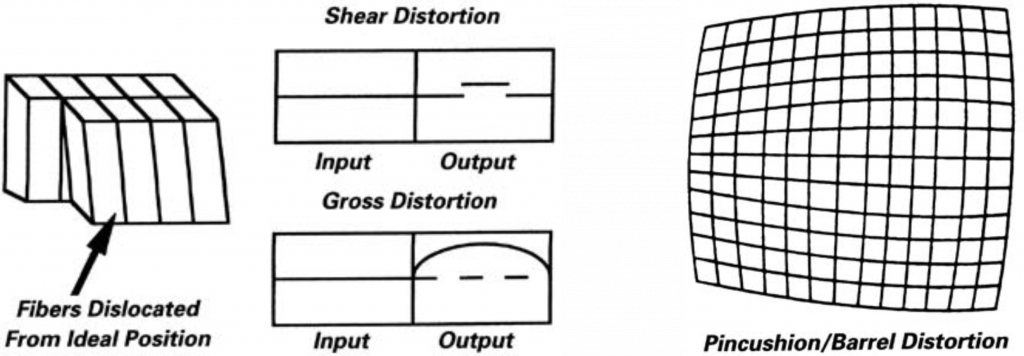
Distortions
There are two types of distortions: shear distortions and gross distortions. Shear distortions are caused by misalignment of multi-multi fibers along the length of a fusion. They are the lateral displacements that cause a straight line to be imaged as a “break”. This results in a small break in the coherency of the image in the final component.
Gross distortions are caused by material flow in the fusing operation. They are defined as distortions that cause a straight line to be imaged as a continuous curve. Proper control of temperature and pressure during pressing can minimize this kind of distortion, which is defined as the maximum displacement from a straight line.
Further Information
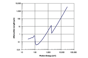
Utilizing Phosphors for Indirect Detection of X-rays
Technical note describing the two types of phosphors used for x-ray imaging applications between the energy ranges 5 keV and 50 keV.
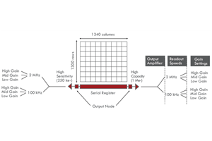
Flexible Electronic Architecture Extends Camera Utility
Technical note describing how flexible electronic architecture can be advantageous for multiple applications within x-ray research.
Direct Detection of X-rays using CCD Technology
The fundamentals of CCD technology and how it is optimized for the direct detection of x-rays.