
Introduction
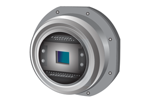
Imaging in the infrared brings unique challenges. The NIRvana range of InGaAs cameras from Princeton Instruments operates in the Short-Wave InfraRed (SWIR) or second Near Infrared (NIR-II) region from 900 nm to 1700 nm. Sensitivity to wavelengths in this range unlocks a whole host of applications within scientific research. Scientific applications typically demand the very best imaging performance that SWIR can deliver. Industrial SWIR applications and cameras to meet them are also common, but considerably less demanding in their imaging needs.
One key differentiator between scientific and industrial SWIR cameras is the image quality resulting from reduced noise. InGaAs as a technology inherently features higher read noise and thermal, exposure-dependent dark current than silicon-based sensors. However, in demanding applications, the actual performance of SWIR cameras requires considerations beyond these conventional ‘specification sheet’ values.
A unique challenge in infrared imaging is that SWIR photons are, in fact, everywhere. We aren’t of course able to see them to allow us to easily trace and eliminate background photon sources. But all background light contributes background noise, which can in many cases outstrip camera-based noise sources depending on the severity. Indeed, due to blackbody radiation, all room temperature objects are constantly emitting SWIR photons, as are the electronic circuits and housings of SWIR cameras. How do we block these photons from obscuring our intended signal?
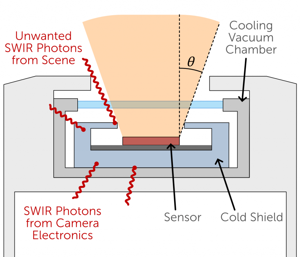
The answer is Cold Shielding. Through limiting the angles with which photons can reach the sensor to only the frontal angles the sensor is pointed at, extraneous photons from the environment are minimized. This cold shield is so named because it is cooled to the same low temperature as the sensor, hence emitting no blackbody radiation in the SWIR range itself. This article will explore how cold shielding is critical for low-light scientific SWIR imaging, and discuss the cold shielding featured in the NIRvana range of cameras from Teledyne Princeton Instruments.
Background Signal is Background Noise
What is the drawback of background light? Surely a sufficiently accurate ‘background subtraction’ can eliminate the contribution of background photons? In fact, although this step is essential in quantitative imaging, the worst contribution of background signal is still present after subtraction: photon shot noise from these background photons.
If you’re not familiar with Photon Shot Noise, this is the noise source inherent to the random nature of photon emission and detection. Practically all photon sources do not emit individual photons at precise, regular intervals. Instead, photons are emitted randomly in time, though perhaps with some known average rate. Even within the pulses of a pulsed laser, individual photons will be randomly distributed in time around some known average distribution. This randomness means that should we attempt to measure the light detected from an object, there will be a variation from measurement to measurement – i.e., noise is introduced. This random behavior with known average follows what’s known as Poisson statistics, and like all Poisson behaviors, the noise contribution in a measurement counting events (photons) is given by the square root of the number of counts. The total photon shot noise in a pixel then:
What this means then is that our background light, whatever its source, is adding its photon shot noise to our inherent camera noise sources. It is entirely plausible for noise from background light to be orders of magnitude larger than camera noise sources in high-precision experiments. So, what are the most significant sources of background light, and what can be done about them?
Light Leaks
Even when dealing with visible light many optical setups, especially on open-top lab benches, must deal with the challenges of avoiding light leaks from the room, laser reflections, computer screens, and light from LEDs on components. What if the background light you’re trying to trace wasn’t even visible to your eye? Tracing infrared laser paths and aligning components can be a significant challenge in infrared, and any unwanted background light that makes its way to the camera sensor will add to the challenge of detecting signals of interest.
There are two methods to improve this issue. The first is painstaking and long-winded experimental optimization to remove possible sources of infrared photons. The second is to use a camera that limits the range of angles with which incoming background photons will be detected from through the use of cold shielding. When a camera sensor is properly shielded from external radiation, the range of tweaks to an optical setup that are required to minimize background light will be much reduced.
Blackbody Radiation
At room temperature, all objects in a typical room will in fact be emitting infrared photons due to blackbody radiation. Blackbody radiation is the emission of photons from any object in thermodynamic equilibrium with its environment.
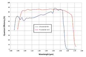
The objects in an optical setup, surrounding objects in the room, and most especially any objects that are warmer than room temperature such as equipment, computers, and people, will be emitting a barrage of photons that the camera is sensitive to. The graph below gives an indication of the emitted photons per unit solid angle at 300K (27°C), per square centimeter of the object’s surface, versus photon wavelength, per second. As you can see, this number approaches 150 million photons per second towards the higher wavelength end of the spectrum.

Figure from https://opticsthewebsite.com/OpticsCalculators
Emission from camera housing & electronics
Cold shielding isn’t just for objects in front of the camera. It shields the sensor from photon emission inside the camera too. The heat dissipation from the cooled sensor will, of course, partially take the form of infrared photons. Especially for parts of the camera housing that sit in front of the sensor, these photons can be detected by the sensor.
What’s more, the normal operations of electronic circuits can in fact produce infrared photons. The only solution to avoid detection of these photons is to introduce cold shielding that separates the sensor from the rest of the camera circuitry and housing. It is therefore important that cold shielding not only limits the incoming light cone, but also wraps around and behind the sensor. The level of camera-derived thermal emission will also vary from camera to camera. The NIRvana range of infrared cameras are specifically designed to minimize thermal photons from the camera electronics reaching the sensor through world-leading thermal management engineering. When combined with cold shielding, the performance of the NIRvana range has to be seen to be believed.
NIRvana’s Cold Shielding
The NIRvana range of SWIR cameras from Teledyne Princeton Instruments are specifically designed for demanding scientific applications, and as such have cold shielding as standard. The form this takes is a physical barrier that sits in front of, around and behind the sensor, restricting the incoming photons to only a specified cone around the optical axis of the sensor. This shield sits inside the hermetic-sealed vacuum chamber of the NIRvana cameras and is cooled to the same industry-leading low temperatures as the sensor. This provides unparalleled protection from unwanted photons, and hence unwanted noise.
A representative diagram of where the cold shielding sits is shown in Figure 2.
f/#: Cold Shield Specifications
The specification seen on camera datasheets for cold shielding is a f/# number, an aperture specification familiar from lens-based optics. To convert this value into a more intuitive light cone half-angle, as illustrated in Figure 2, use the following formula:
Where n is the refractive index of the medium, in this case air, . Using this formula, we can calculate the following light cone angles for the NIRvana series of cameras:
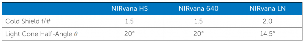
Any extraneous background light arriving at the camera outside this light cone, or any SWIR photons emitted by the warm camera housing in front of the camera will not be detected.
Summary
SWIR photons are all around us and are even emitted by cameras themselves. Through providing a deep-cooled physical barrier between the sensor and these photons, NIRvana’s cold shielding cuts out the additional noise contributions of background signal, allowing higher signal to noise ratios and the highest image quality.
Further Reading
How NIRvana Cameras Keep Their Cool
Find out about the industry-leading thermal management performance of the NIRvana InGaAs camera range
The Powerful Sensitivity of NIRvana Cameras
Find out more about how the NIRvana range improves signal-to-noise-ratio and provides powerful sensitivity.
Image corrections in SWIR
Find out more about the common imaging artifacts that InGaAs sensors exhibit, and how the NIRvana range combats them.