Introduction
Intensified cameras are specialized devices that optically connect an image intensifier to a CCD sensor. One finds a wide variety of CCD sensor architectures making this camera type adaptable to many imaging and spectroscopy experimental needs.
PI-MAX4 intensified CCD cameras use 3 different types of CCDs: front illuminated CCDs, interline CCDs, as well as F/I and B/I electron multiplying CCD sensors. Particularly this latter type, the emICCD camera, increases the sensitivity, linearity, speed and flexibility compared to its standard ICCD counterparts.
When considering an emICCD camera for an experiment it is useful to understand the specific advantages it has and how it performs in concrete measurement scenarios. In addition, the high performance of emICCDs has been shown in multiple, published scientific articles. In the following we will briefly describe how ICCDs operate, when they are used and explain the advantages of using an emICCD camera highlighting specific applications.
Why use an ICCD?
Image intensifiers combine the ability to amplify an incoming photon signal with an extremely fast electronic shutter, called an electronic gate. ICCDs achieve on/off switching times down to sub nanosecond timescales. They have found widespread use for scientific imaging and spectroscopy applications. Experiments typically require ICCD cameras for
one or several of the following reasons:
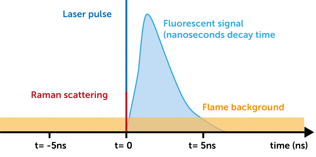
• Suppression of bright, continuous background signal. A major application area of scientific ICCD cameras is the study of the internal dynamics and chemistry of combustion flames. The atoms in the combustion flame can be probed with an ultra-short laser pulse to excite fluorescence. The ICCD gate can be triggered to open immediately after the laser pulse for the short time the laser induced fluorescence signal is larger than the continuous background radiation, that would overwhelm the signal on longer timescales (see Figure 1).
• Resolve ultrafast (< 1ns) and dynamic phenomena. An ultrafast shutter allows acquisition of snapshots of ultrafast dynamics on the ns timescale for example, the time evolution of a plasma discharge or shockwaves in materials. ICCDs can also measure fast fluorescent decay times. ICCD cameras have a super precise and accurate timing and trigger system that allows for timing control of the gate opening relative to other parts of the experiment (typically on the level of a few picoseconds).
• Amplification of signal. All ICCD cameras can apply a gain to the signal before readout, enabling detection of low light signals. Amplification increases the signal above the read noise levels of the camera. While the amplification stage in ICCD cameras is provided by the image intensifier (intensifier gain), emICCD cameras have an additional on chip multiplication gain stage that can be operated simultaneously. The PI-MAX intensifier gain is calibrated by the number of photoelectrons that will be detected on the camera sensor, between 1-100. Note that the amplification is a stochastic process so for a given gain level the number of photoelectrons per detected photon will fluctuate (this actually contributes to additional noise in the camera, so called excess noise). When EM-Gain is applied on top of intensifier gain, amplification of 10,000 times can be achieved.
Components of an ICCD
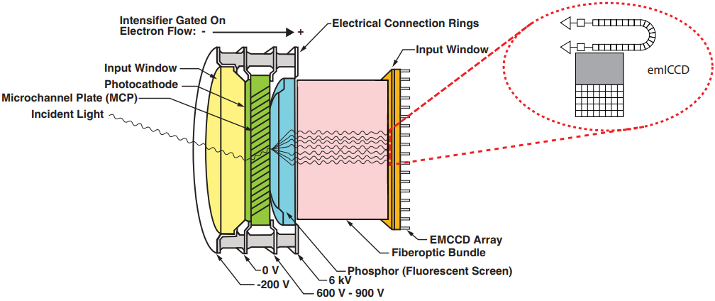
What components in an ICCD camera contribute to its properties of suppressing background, ultrafast shuttering and signal amplification? Here is a short overview of the components in an ICCD camera.
Figure 2 shows a schematic view of the components of an image intensifier:
• Incoming light will first expose the photocathode of the image intensifier. The photocathode is converting the incoming light into electrons due to the photoelectric effect. The process of gating in the ICCD consists of applying a voltage between the photocathode and the microchannel plate. It will either block the photoelectrons from travelling through the intensifier or accelerate them towards the remaining components of the intensifier. The photocathode ultimately determines the quantum efficiency of the ICCD. Various choices of photocathode types and materials are available, optimizing the camera for operation in specific wavelength bands from UV to NIR.
• The electrons generated in the photocathode will next encounter the micro-channel plate (MCP). The MCP consist of millions of channels with diameters of a few micrometers containing a secondary electron emitter. Applying a high voltage across the MCP accelerates the incoming electrons, leading to a cascade of secondary electron emission upon collision with the walls of the channels. The ratio of outgoing to incoming electrons, the gain of the camera, can be controlled by the increasing the voltage applied across the MCP.
• The intensified image is generated on a phosphor screen after the MCP where the amplified electron signal is converted into photons upon impact with the phosphor. Different choices of phosphors are available for image intensifiers. The emitted fluorescence signal will decay with a phosphor characteristic lifetime.
• For detection, the intensified image generated on the phosphor needs to be optically transferred to the sensor by coupling with a lens or a fiber-optic bundle. Lens coupling offers some advantages in cost and flexibility but leads to high losses of light. While some light losses can be compensated by increasing the MCP gain, this leads to nonlinear response of the camera (see below). Fiber optic coupling increases light throughput and reduction of stray light making it the preferred method for sensitive detection.
• The intensified image is finally detected on the camera sensor. The specific advantages of choosing an EMCCD sensor compared to a conventional CCD sensor are described in more detail below. In difference to conventional CCD cameras the quantum efficiency of the ICCD sensor is a less considered parameter as the QE is determined by the photocathode on the intensifier. However, the QE of the sensor can affect the linearity of the camera (see
below).
The resolution is lower on an ICCD camera than on a CCD camera. It is limited by the image intensifier to around 64 line pairs per mm or less. It is best to match the spatial resolution of the intensifier with the pixel size of the camera sensor (between 13-16µm). Smaller pixel size will not provide additional advantages for the resolution of the camera, but potentially negatively affect linearity and sensitivity.
Detailed understanding of the components of an ICCD camera is very useful for evaluating a particular choice of camera for a specific application. We recommend the PI-MAX4 Brochure to find more detailed information about how gating works, different types of photocathodes, phosphors and their performance as well as a detailed comparison of advantages and disadvantages between fiber coupling and lens coupling of fiber coupling over lens coupling.
Reference:
• PI-MAX4 Brochure
The advantages of using an emICCD
emICCDs combine advantages of EMCCD and ICCD cameras to achieve performance beyond the limits of each individual technology. So, what are the specific reasons one should choose an emICCD for their measurements?
High gain increases sensitivity for low light to single photon imaging
Signal amplification is an important mechanism for detection of low light signals. Essentially it increases the incoming signal above the noise levels of the camera. While amplification for EMCCD sensors happens in the EM-gain register and in the MCP for ICCDs, emICCDs have the unique ability to apply both gain mechanisms simultaneously. The gain factor in each stage multiply and the ultimate achievable gain is increased by an order of magnitude when using both gains. Not all applications require the maximum applicable gain and it can be a good idea to optimize the camera
performance for a specific application by fine tuning the individual EM and intensifier gain levels.
Example: EMICCD comparison for low light imaging
While the increased gain should lead to higher sensitivity in low light situations in theory, it is most instructive to directly observe the advantages of an emICCD system in low light level applications, by directly comparing to a “standard” ICCD system in identical measurement situations. This was exactly achieved in a 2015 article by Andreozzi et al. where different camera systems were evaluated for imaging the Cherenkov emission for monitoring radiation therapy of tumors.
Cherenkov radiation is produced by ionizing radiation in the body during treatment of subsurface tumors. Measuring this radiation can be related to the position dependent deposited energy dose. This makes Cherenkov imaging a useful tool to monitor treatment success and potentially control treatment in real time.
Cherenkov imaging with ICCDs makes use of the strong suppression of background radiation. Pulsed high energy radiation from an accelerator will produce ultrashort flashes of Cherenkov light. With an ICCD imager the room lights can be left on during treatment in a way to increase patient comfort who would otherwise have to be exposed to “complete” darkness using ordinary cameras.
Andreozzi et al tested an emICCD against an otherwise identical ICCD camera (same camera mode and intensifier) as well as an ICCD with different intensifier. The article concludes that “the EM-ICCD definitively outperformed all other cameras examined in this study for performance at clinical Cherenkov imaging in terms of both speed and sensitivity.” In particular the EMICCD was the only camera that achieved the desired signal to noise ratio target using single shot acquisitions (not accumulating the emission of multiple radiation pulses).
Reference:
• J. Andreozzi et al, „Camera selection for real-time in vivo radiation treatment verification systems using Cherenkov imaging”, Medical Physics 42, 994(2015)
Example: Single photon imaging and quantum imaging
Amplification by charge multiplication is a stochastic process for both EMCCD gain as well as MCP gain schemes. For any incoming photo electron there is a distribution of probabilities for detection of a certain number of output electrons.
• Stochastic process of amplification causes additional excess noise that affects the signals of amplifying cameras.
• The signal to noise ratio of EMCCDs and ICCDs is worse for medium to high signals due to excess noise.
• Finding the actual number of incoming photo electrons based on the detected signal is not possible except for ultra-low photon fluxes where the number of photons per pixel per image is less than 1. This is the basis for single photon imaging.
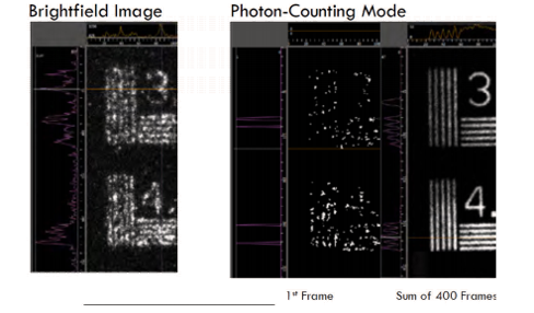
Single photon imaging uses a thresholding scheme effectively eliminating excess noise and improving imaging performance (see Figure 3). Compared to standard ICCDs and EMCCDS, the emICCD achieves a higher likelihood of positive detection of a single photon due to the much higher gain. Higher likelihood shortens the observation time and increases image quality
Unlike ungated detectors, emICCDs can apply both a high gain level and ultra-short gate width. Gate-ability also allows for synchronization of the image acquisition of an emICCD to a specific time window where an incoming photon is experimentally expected. An important application for quantum research are measurements involving entangled photons.
In a 2020 article Schwarz et al describe using an emICCD for coincidence detection of single, entangled photons with 3ns gate width (investigating the so-called Talbot effect on single photons). The group says that empirical tests established a gain of 9000 giving “clear features for measurements with a high signal to noise ratio”. However, this gain level would not have been achievable using a conventional ICCD camera.
References:
• S. Schwarz et al., “Talbot Effect of orbital angular momentum lattices with single photons”, Phys. Rev. A 101, 043815 (2020)
• R. Xu, “Quantum experiments with single-photon spin orbit lattice arrays”, Masters Thesis, University of Waterloo (2019)
Combined gain eliminated non-linearities and increases dynamic range
Non-linearities in ICCDs mainly arise saturation due to charge depletion in the MCP channels, if electrons from the channel walls that contribute to the amplifying electron avalanche can’t be replenished fast enough. For standard ICCDs non-linearities can significantly influence their dynamic range and potential for quantitative measurements.
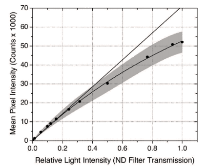
Non-linearities can significantly limit the dynamic range of an ICCD. In the measurement shown in Figure 4 from William et al, the dynamic range of the camera is limited to 25% of the maximum 16bit range of the A/D conversion. In addition to the limited dynamic range, calibration of the camera to account for the non-linear response in quantitative measurements is difficult as the response of the camera depends on parameters that are often changed such as the intensifier gain.
In a 2012 article Linden et al investigate the limits of traditional ICCD cameras. Their experiment uses a thermographic phosphor where the ratio of emission at 2 separate wavelengths is used as a measure for temperature. The article describes that “saturation within the intensifier is usually not a concern when performing qualitative measurements; however quantitative measurements […] are easily affected by small nonlinearities”.
The ICCD response is characterized using a series of neutral density filters to allow exposure of the ICCD with different light intensities. Linden et al show that due to the non-linearity of the ICCD camera the “trade-off between useable irradiance and gain corresponds to a number of counts less than half the numerical range of the A/D converter”.
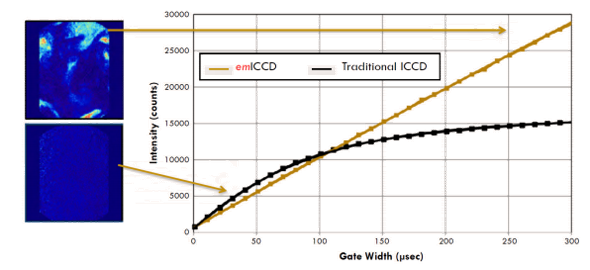
Non-linearities of an ICCD are most severe at high gains and running the camera at low gain leads to a more linear response. emICCD cameras can significantly increase the linearity and dynamic range compared to standard ICCD cameras as a lower intensifier gain can be compensated by applying additional gain on the EMCCD sensor of the camera.
For example, ICCD applications that require fast times between individual image frames require a fast decaying phosphor on the intensifier. P46 phosphor has a decay time of 2µs to 1% of maximum intensity, but its light emission is not as optimal for readout with a CCD as P43 phosphor which has a much longer life time of 3ms. The loss in sensitivity can be easily compensated by applying a higher intensifier gain which increases the non-linear response in traditional ICCDs. In emICCD cameras the intensifier gain can be kept at a lower lever while additional em-gain will compensate for the loss in sensitivity.
Figure 5 shows the impact of using the additional EM-gain of the emICCD camera. The figure shows images of laser induced fluorescence emission of residual exhaust gases (such as CO, NO, OH, etc.). The intensity response of an emICCD shows positively increased linearity as the input signal is increased compared to a traditional ICCD camera for increasing intensity. The images demonstrate the increase in dynamic range allowing for more detailed contrast for high intensity images.
References:
• J. Linden et al, “Limitations of ICCD detectors and optimized 2D phosphor thermometry”, Meas. Sci. Technol. 23, 035201 (2012)
• T. C. Williams et al, “Simultaneous correction of flat field and nonlinearity response of intensified charge-coupled devices”, Rev. Sci. Instr. 78, 123702 (2007)
• “emICCD: The Ultimate in Scientific ICCD Technology”, Princeton Instruments Technical Note (2013)
High image and spectral rates
emICCDs not only increase sensitivity, linearity and dynamic range, but can operate at high speeds required for capturing dynamic processes. emICCDs can operate at frame rates of >300fps at reduced resolution and at >10,000 spectra per second in spectroscopy applications.
For example, Dr. Jun Kojima of the Ohio Aerospace Institute and his colleages from NASA Glenn research center use these capabilities to measure combustion dynamics in flames with higher SNR and dynamic range (see referenced application note for all details about the measurement technique). Dr. Kojima built a new experimental setup for spontaneous Raman scattering spectroscopy to measure the temporal variations of different combustion gases (oxygen, nitrogen and water vapor) and their behavior in unstable flame dynamics. The image intensifier of the emICCD camera is synchronized with a pulsed laser running at 10kHz and operated at 90ns gate width (for suppression of the flame background while optimally capturing the signal).
While running at spectral rates of 1kHz, the measurements with the emICCD camera show higher signal visibility and SNR compared to previous measurements. The increase in sensitivity is attributed to the gain and linearity of the camera.
Reference:
• Application Note on time-resolved spontaneous Raman scattering spectroscopy: Ultra-High-Speed, Time Resolved Spontaneous Raman Scattering Spectroscopy in Combustion
Track record of published scientific research
Scientific cameras ideally enable new scientific research and discoveries. Over the past few years emICCDs have become the camera of choice in applications requiring ultimate performance, and quality necessary for measurements in cutting edge research. Applications using emICCDs span across a wide range from combustion and plasma physics to material and life science imaging and spectroscopy. Here is a short overview of some of the applications with lists of selected references where emICCDs were used for data acquisition.
Combustion
Combustion research investigates the physics and chemistry of flames. Gated detection is used to suppress background radiation of flame while isolating the laser induced emission of the combustion gases. Combustion uses techniques such as planar laser induced fluorescence (PLIF), Raman Scattering, Chemiluminescence and laser induced incandescence to measure the concentration and state of the different molecular species.
Plasma Physics and Monitoring
Plasmas have wide applications from fusion research, material deposition, environmental and life science and others. Increased understanding of the fundamental processes in plasmas and their dynamics will lead to new and optimized applications in these areas. emICCDs are used for imaging and spectroscopy with nanosecond time resolution to take snapshots of the state of the plasma. Emission spectroscopy and Thomson scattering can characterize plasma parameters such as its temperature.
Life Science
Various applications in life science imaging and spectroscopy use intensified cameras for their capability of high time resolution to isolate signals and suppress background radiation. Applications include Cherenkov imaging to control radiation therapy, fluorescent lifetime imaging (FLIM), and non-linear optical techniques such as second-harmonic imaging.
Materials Science and LIBS
emICCDs detect time resolved emission and fluorescence signals from materials and nanostructures. Laser Induced Breakdown Spectroscopy (LIBS) analyses the composition of materials. Time-resolved measurement of photoluminescence is an important technique to understand new materials such as perovskites for solar cell applications. The high time resolution of emICCDs is also used to investigate rapid structural changes in materials induced by collision and impact of projectiles
Quantum Research
Single photon sources and entangled photons are important pieces of quantum devices and measurements based on the quantum nature of materials. High gain and sensitivity as well as the fast gating capabilities of EMICCDS are optimal for detection of single and entangled photons.
| Author | Title | Year |
| Schwarz et al. | Talbot effect of orbital angular momentum lattices with single photons | 2020 |
Other applications: Physics, Chemistry, Nonlinear-Optics, Standoff Raman spectroscopy
Conclusion
The combination of EM gain, intensifier gain, high sensitivity and speed make an EMICCD camera one of the most flexible intensified camera choices that can adapt to various and even changing measurement configurations. emICCDs combine the best of 2 cameras: sensitive detection as in EMCCDs combined with fast gating and high time resolution of ICCDs.
Additional application information can be found at: https://www.princetoninstruments.com/products/pi-max-family/pi-max/app-notes
