
Overview
»While many labs use LabVIEW for instrument automation, quite often researchers find it daunting to create their own vi’s if a sub-vi for a desired function is not provided by the instrument manufacturer.
» Teledyne Princeton Instruments provides robust documentation and building blocks to help most users perform their desired automation without any extra effort needed.
»When the sub-vi for a desired function is not already provided, it is still very straightforward to walk through the documentation provided by Teledyne Princeton Instruments in order to plan the necessary workflow and then execute it in LabVIEW.
»Here, we use a case study implementing the automation of custom region of interest in order to demonstrate and teach the principles that apply to any desired automation function.
Getting Started with the Provided Resources
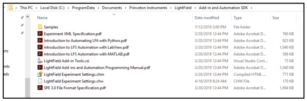
Upon performing a complete installation of Teledyne Princeton Instruments LightField®, a “LightField Add-in and Automation SDK” folder will be created in the “C:\ProgramData\Documents\Princeton Instruments\LightField\Add-in and Automation SDK” path (Fig. 1).
Please use the step-by-step guide (titled “Introduction to LF5 Automation with LabView.pdf”) to get acquainted with the process for beginning an automation project using LabVIEW, as well as for instructions on how to locate and use the many sub-vi building blocks that we provide. In the vast majority of cases, you will be able to automate and execute your desired functions utilizing these provided sub-vi’s.
Automation of functions outside the scope of our included sub-vi’s
While our included sub-vi’s will allow you to automate virtually all functions needed by a typical user, there may be some cases where additional functions need to be automated. Since many LabVIEW users are not familiar with .NET development (and they don’t need to be in order to accomplish their goals!), a task that should be simple in principle can end up becoming a challenging time sink.
Here, I will use a case study showing the implementation of a custom region of interest to demonstrate the principles of automation via LabVIEW. These principles will apply to all functions supported by the automation interface.
Step 1: Create a basic framework for testing individual sub-vi’s.
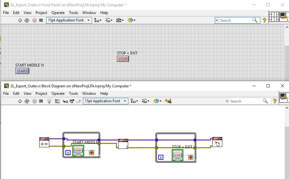
The most important step in debugging anything is to set up an environment where the variable being tested is isolated. The same applies for LabVIEW automation. Therefore, my first recommendation is to set up a test vi where one can plug in the newly created vi and test its function within LightField. Fig. 2 shows a setup that I like working with. Here, I plug a newly created sub-vi into the middle of the two while loops. Running the vi from LabVIEW creates an automation interface and brings up a LightField window on the screen. I can now add whatever equipment I need for the vi into the LightField workspace. Then, when I hit “Start” on the LabVIEW block diagram, it executes the vi in the middle exactly once. I can thus verify that the setting I wanted to change did indeed change in LightField. Then, I exit and clear memory with the “Stop” button from the front panel.
Step 2: Create a new sub-vi with automation inputs and outputs.
You may have noticed from Fig. 2 that the sub-vi being tested has two inputs and two outputs; these are an automation in/out and an error in/out. You can create a new sub-vi to have the same properties by simply copying over an existing vi and then modifying its inner contents.
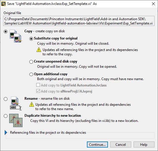
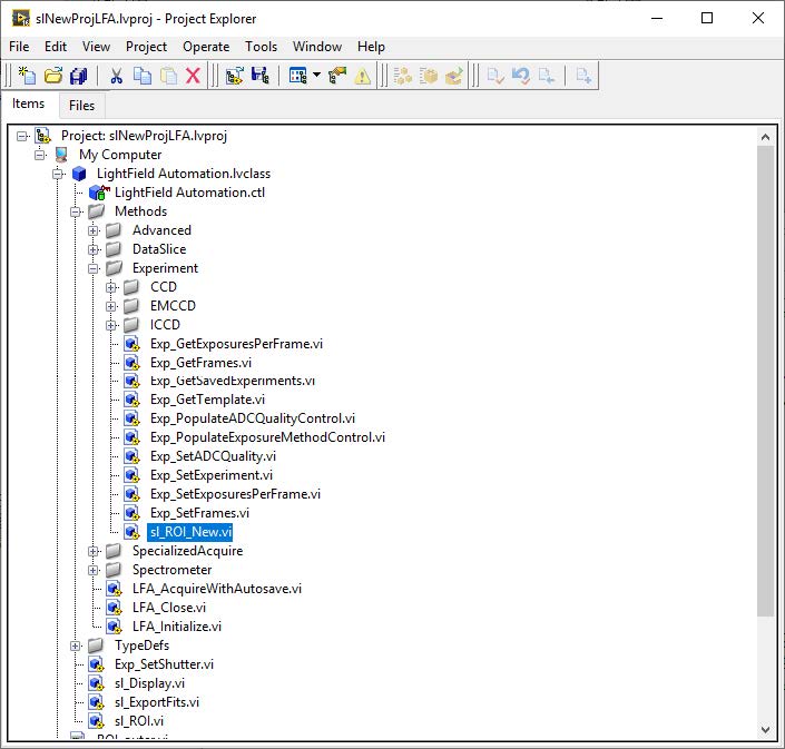
So, let’s do this! From the project window, open the block diagram for the already provided “Exp_SetTemplate.vi”. Go to File -> Save As… and make a copy of the vi on disk. You can select Substitute copy for original -> Continue… -> create name for sub-vi. After saving, the original vi will be closed and the new copy of the vi will remain open. You should see the new vi you saved under the LightField Automation.lvclass tree. Fig. 3 illustrates these steps
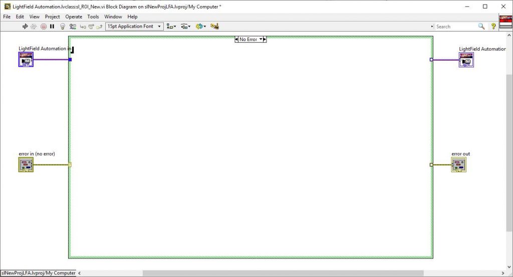
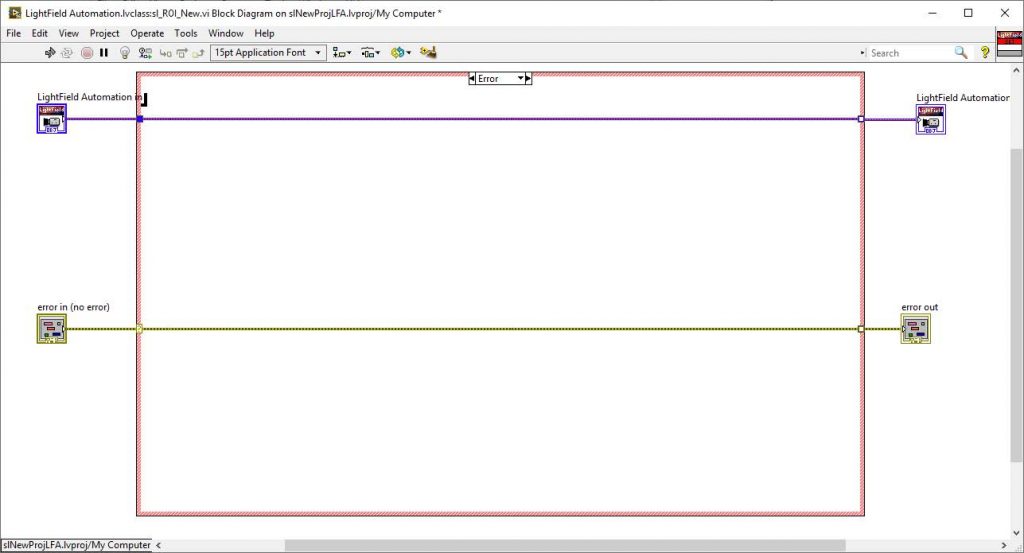
After creating this new vi, you can clean up everything that is inside the case structure; we will fill everything in from scratch for this case study. Leave only the automation / error inputs and outputs, as well as the No Error / Error case structure boundary, and delete everything else (Fig. 4).
Step 3: Determine the objects, methods, and properties needed for the desired function.
Now that we have a fresh canvas on which to work, we can proceed with filling in the needed blocks for the Region of Interest function. First, we will check the “LightField Add-ins and Automation Programming Manual.pdf” that is provided by the LightField installer (please refer to the Getting Started with the Provided Resources section of this bulletin).
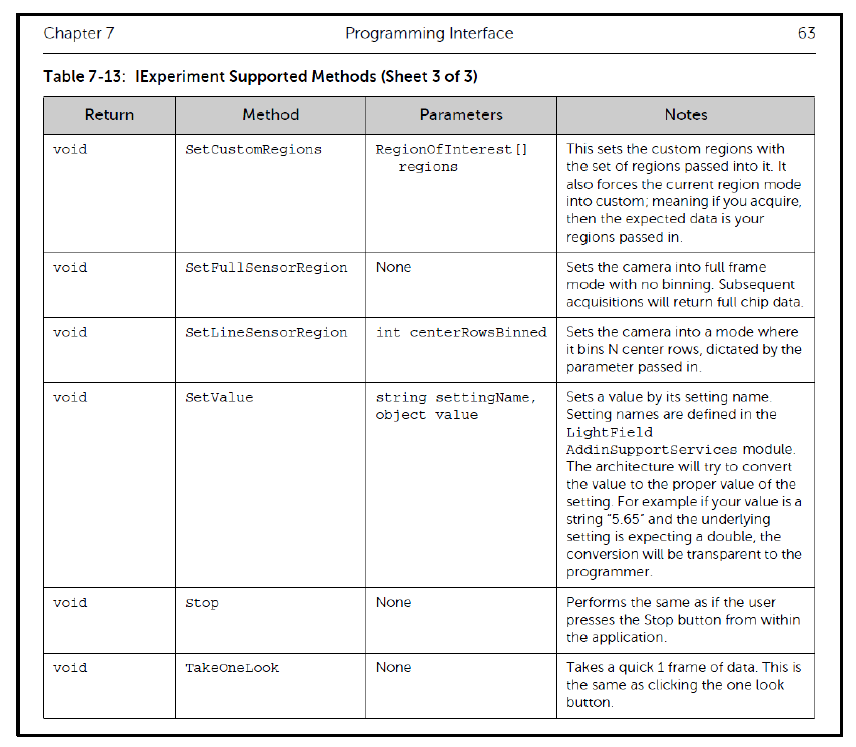
From a search through this document, we find that the IExperiment interface has a methodncalled “SetCustomRegions” that requires an input of “RegionOfInterest [] regions” – you can find this on pages 61–63.
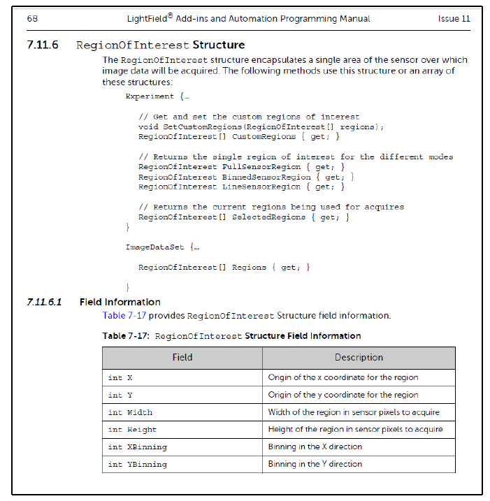
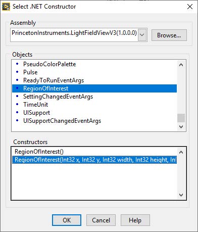
A further search shows that the RegionOfInterest structure is defined on page 68, section 7.11.6 (Fig. 5). Thus, in order to set a custom region of interest via automation, we would need to do the following:
- Create an instance of the IExperiment interface.
- Create a RegionOfInterest structure with the x, y, width, height, xbinning, and ybinning parameters defined.
- Add the structure created above to an array.
- Call the “SetCustomRegions” method using the array created in the above step as an input.
Step 4: Execute the workflow from Step 3 with LabVIEW blocks.
Now we are finally getting to the LabVIEW action. It is quite simple. We will just translate the process derived in Step 3 with the appropriate LabVIEW blocks to fill in the “No Error” case of the new, blank vi that was created in Step 2.
Here, I will go through each item from Step 3 to show how to execute the plan in LabVIEW:
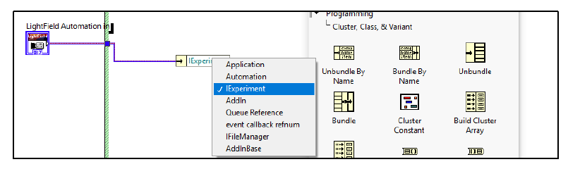
- Insert an Unbundle by Name block with LightField Automation in as the input. Select “IExperiment” as the interface.
- Create a .NET constructor (Connectivity ! .NET ! Constructor node). The
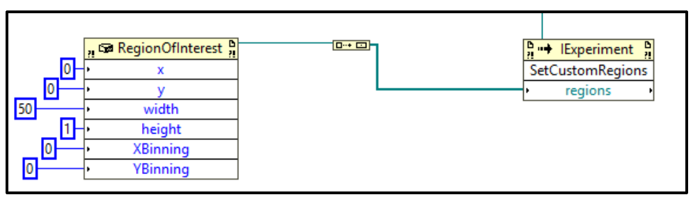
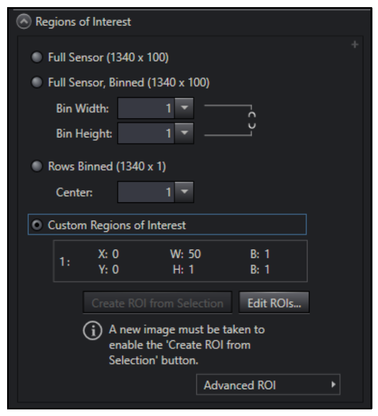
RegionOfInterest structure needed will be part of the PrincetonInstruments.LightFieldViewV3 assembly. For test purposes, make all inputs constant integer with the following values: x: 0, y: 0, width: 50, height: 1, xbinning: 1, ybinning: 1. - Use “Build Array” block to generate array from the RegionOfInterest.
- Create a .NET Invoke node (Connectivity ! .NET ! Constructor node) to take a reference from the unbundled IExperiment interface, select the “SetCustomRegions” method, and input from the array in Step 3.
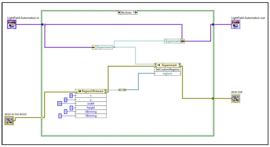
That’s it! Now just wire the error flow through the .NET nodes, re-bundle the IExperiment interface (Bundle by Name block) and connect to the outputs as needed. Please refer to Fig. 6 for a breakdown of the above processes and to Fig. 7 for a look at the final sub-vi block diagram. We are now ready to test the newly created sub-vi.

Step 5: Test the newly created sub-vi.
Place the newly created vi into the test framework created in Step 2, with inputs and outputs wired to complete necessary connections (if necessary, refer to Fig. 2). Start the main vi to create and open a LightField automation instance, then load in a live/demo camera to the experiment workspace and make a note of the default ROI setting (it should default to Full Frame). Once you are ready, run the sub-vi and verify that the region of interest changes as expected. Fig. 8 shows the before and after when running the newly created sub-vi within the test framework after loading a Demo BLAZE:100B camera set for 1-port readout.

Conclusion
It need not be daunting to create a sub-vi to automate a desired function that is not already provided in the sample repository installed by LightField. While the case study above takes us through the specifics of setting up a custom region of interest, these principles will apply to any function one is trying to automate. Should one still be stuck after reviewing the documentation included with LightField, as well the material in this technical bulletin, the support team at Teledyne Princeton Instruments will be happy to help! Our team consists of Ph.D.-level engineers who are enthusiastic about the cutting-edge applications performed by the brilliant minds who use our products. We will help you bridge the gap between software and science. Please feel free to reach out to us by filling in a Support Contact Form.
Further Reading

LightField Tips and Tricks
Handy guide focusing on different features within LightField to enhance user experience.
Automating Acquisition with MATLAB During Temperature Changes
A guide on how to automate data acquisition in respect to changing camera temperature using MATLAB software.
Automated Wavelength and Intensity Calibration to Improve Spectra
Article describing the advantages of IntelliCal wavelength and intensity calibration with LightField