
Technical Information about EMCCDs, emICCDs, and InGaAs Array Cameras
Overview
Quantum theory seeks to explain the nature and behavior of matter and energy at atomic and subatomic levels. Quantum research aims to manipulate the state of this matter and energy to achieve accurate, measurable, and repeatable results, thereby improving the understanding of such phenomena.
Most modern quantum research activity focuses on how to apply fundamental quantum principles (e.g., superposition and entanglement) to develop new technologies for use in fields such as computing, communications, and sensing. Optical manipulation and detection play key roles in realizing these applications, which include experiments on atom/ion traps, superconductors/semiconductors, quantum dots, carbon nanotubes, photonic systems, neutral atoms, and nitrogen vacancy centers in diamond. Measurements often require the detection of molecules and atoms down to the single-particle level. This work necessitates utilization of extremely low signal thresholds as well as data acquisition with low noise at high frame rates.
For measurements in the visible (VIS) to the near-infrared (NIR) wavelength range, EMCCDs and emICCDs have established themselves as the optical detectors of choice for emerging quantum research applications. Scientific InGaAs detectors, meanwhile, are often employed to extend the limit of optical detection into the higher, short-wave infrared (SWIR), which is an important wavelength range for telecommunications.
This document describes several technical considerations that allow cameras to operate down to the single-photon level and presents examples from real-world applications.
Electron-Multiplying CCDs (EMCCDs)
EMCCDs are high-sensitivity CCDs engineered to address the challenges of ultra-low-light imaging applications — without the use of external image intensifiers. EMCCDs use on-chip electron-multiplying (EM) gain technology to multiply photon-generated charge above the read noise for all frame rates.1
This special, signal-boosting process occurs before the photoelectrically produced charges reach the on-chip readout amplifier, effectively reducing the CCD read noise by the EM gain factor, which can be greater than 1000x. The main benefit of the technology, therefore, is a far better signal-to-noise ratio (SNR) for signal levels below the CCD read-noise floor.1
Gain Mechanism in EMCCDs: Reducing Effective Read Noise
The principal difference between an electron-multiplying CCD and a traditional CCD is the presence of a special extended serial register, known as a multiplication register, in the EMCCD. See Figure 1. The EM gain occurs after photons have been detected in the device’s active area.1
Electrons are accelerated from pixel to pixel in the multiplication register by applying higher-than-typical CCD clock voltages (up to 50 V). Secondary electrons are generated via an impact-ionization process that is initiated and sustained when these voltages are applied. The EM gain can be controlled by increasing or decreasing the clock voltages; the resultant gain is exponentially proportional to the voltage.1 An effective read noise of <1 e- rms is achievable.
The signal-to-noise ratio of a CCD with EM gain is given by1
where
S = total number of photons arriving at each pixel
QE = quantum efficiency (fraction of photons detected)
σTotal = total noise in system = √[(S*QE*F2) + (D*F2) + (σR/G)2]
where
D = total dark-related signal (including spurious charge)
F = excess noise factor (typically between 1.0 and 1.4), described later in this document
σR = read noise of detector
G = EM gain factor
The first, second, and third terms of the denominator denote the effective photon (shot) noise, dark noise, and read noise, respectively, as a result of EM gain. Notice that the shot noise and dark noise are both increased by the excess noise factor, whereas the read noise is reduced by the EM gain factor.1
Read noise, which is typically low (2 to 3 e- rms) for traditional scientific-grade CCD camera systems running at slow readout rates, increases to dozens or hundreds of e- rms at high readout rates. In such experiments, read noise becomes the primary limitation of the system. On-chip EM gain, however, overcomes this problem. Thus, EMCCD cameras are very popular for ultra-low-light experiments that require high frame rates.
Some quantum research applications, such as controlling atoms/molecules in optical lattices, use the image data from the sensor to deliver live feedback to the experiment and therefore require almost real-time access to camera data. The Teledyne Princeton Instruments PICam application programming interface (API) offers direct control of our cameras, including fast access to live data via event callbacks. In-house tests demonstrate that full parsing of 1024×1024 frame data on a ProEM-HS:1024BX3 camera (GigE interface) can be achieved in as little as 2 msec after readout ends. Instructions detailing how to set up access to live data are provided in a separate technical note.
Excess Noise Factor
On-chip EM gain is a probabilistic phenomenon, meaning there is a statistical variation in the gain (often, the reported EM gain is an ensemble average). The deviation or uncertainty in EM gain, which is related to the pulse-height distribution found in various scientific literature, introduces some amount of additional system noise, quantified by the excess noise factor F.1
Extensive investigations have been conducted in this subject area. Experimental results show that the excess noise factor is between 1.0 and 1.4 for levels of EM gain as high as 1000x. (When calculating total system noise, both the dark- and photon-generated signals are multiplied by the factor F to account for excess noise.)1
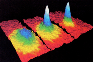
State-of-the-art EMCCD cameras provide the outstanding sensitivity required to perform single-photon detection and single-photon spectroscopy for quantum research. Amplified-signal cameras such as these, which can incorporate an on-chip mask that allows more than 1 million frames per second to be captured when operated in kinetics mode, are also ideally suited for Bose-Einstein condensate (BEC) observations. See Figure 2.
Spurious Charge / Clock-Induced Charge (CIC)
When electrons are clocked (i.e., moved) through the multiplication register’s pixels, the sharp inflections in the clock waveform occasionally produce a secondary electron even if no primary electron is present. This phenomenon, called spurious charge or clock-induced charge, increases slightly as temperature decreases. Exposure time has no effect on CIC.1
Because CIC is very low in traditional CCDs, it is typically ‘hidden’ within the read-noise floor of the camera system. However, for experiments that involve either very low input photon flux (approximately ≤1 photoelectrons/pixel) or photon counting with an EMCCD camera, CIC is the dominant source of noise — owing to the nature of the EMCCD’s on-chip multiplicative gain. Therefore, minimizing CIC in these devices is of much greater importance.
Generation of CIC depends on a variety of parameters, including applied bias level, transfer frequency, and clock rise times. Each of these parameters is carefully calibrated by Teledyne Princeton Instruments in order to balance CIC performance with other specifications (e.g., dark current and charge-transfer efficiency).
In state-of-the-art EMCCD cameras, such as the Teledyne Princeton Instruments ProEM-HS:512BX3, CIC can be as low as 0.002 e-/pixel/frame. Clock-induced charge is minimized when operating at the fastest possible vertical clock speeds, while clock swings are kept as low as practical. Therefore, in order to minimize CIC, the camera should be operated at the fastest vertical shift rates (e.g., 300 nsec for the ProEM-HS:512BX3).
Clock-induced charge can be measured by acquiring dark frames at high gain. The dark image in Figure 3 was acquired with a ProEM-HS:512BX3 using an EM gain of 1000x, an ADC rate of 10 MHz, and a vertical shift speed of 300 nsec. Clock-induced charge is visible in the histogram, creating a long tail in the distribution of intensity values. Next, an event threshold must be selected to determine which intensity values count as CIC events.
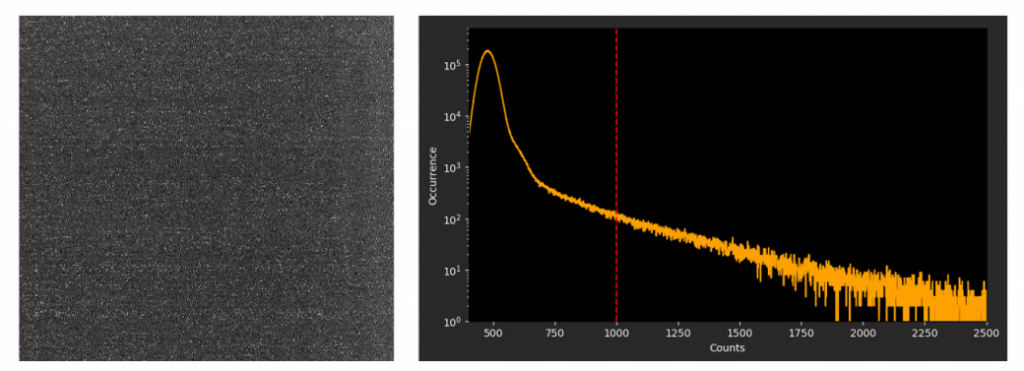
A practical threshold for measuring CIC can be established by identifying the target count level as the ratio G/g between the EM gain G and the output amplifier gain g (as specified on the camera’s certificate of performance), which gives the number of counts above the bias level of the camera. Figure 2 shows a dark image modified by a thresholding function that sets every pixel value above the threshold to 1 and every pixel value below the threshold to 0.
Photon Counting
The low CIC of the ProEM-HS:512BX3 camera makes it exceptionally well suited for photon-counting experiments. Photon counting is a technique ideally applied in ultra-low light flux where the total signal is much lower than 1 photon/pixel/frame. Photon counting is employed to eliminate the influence of excess noise in ultra-low-light measurements.
Photon counting does not measure the total signal per pixel but instead keeps track of the number of single-photon events that occur. Similar to the measurement of CIC described earlier, photon counting is implemented by applying a thresholding function to an image (counting 1 if the signal is above the threshold, or 0 if it is below the threshold). Thresholding functions can be applied either online or in post-processing. Since photon counting cannot distinguish between one or more generated photoelectrons, no benefit is derived from using this technique in higher-flux situations.
Events from dark or spurious charges cannot be differentiated from events generated by photoelectrons; therefore, both the dark noise and the CIC of the detector must be very low for successful single-photon detection. Note that if Teledyne Princeton Instruments is informed that a particular EMCCD camera will be used for single-photon counting, the camera can be optimized for minimal CIC at the factory.
Sensor Enhancement Technologies
Although standard back-illuminated EMCCD cameras are capable of delivering extremely high sensitivity, their performance is compromised by the occurrence of etaloning (i.e., interference fringes). Teledyne Princeton Instruments’ patented eXcelon®3 technology addresses this shortcoming while enhancing the performance of the EMCCD camera system.
Our eXcelon3 sensors provide three significant advantages over other EMCCD technologies:
• Best possible fringe suppression and QE
• As much as 70% reduction in etaloning (i.e., peak-to-peak fringe amplitude)
• Outstanding QE improvement — up to 3x increase in the UV and 1.3x increase in the NIR
Figure 4 presents two series of images showing the etaloning performance of cameras utilizing a standard back-illuminated EMCCD and an eXcelon3 back-illuminated EMCCD, respectively. Years of use in the field have proven that various simplistic approaches — typically the mere utilization of antireflective (AR) coatings — are unable to deliver performance comparable to eXcelon3.

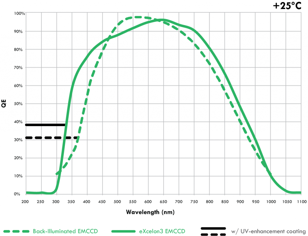
The QE curves presented in Figure 5 illustrate that eXcelon3 back-illuminated EMCCDs provide higher sensitivity below 475 nm and above 625 nm than standard back-illuminated EMCCDs. For the broadest wavelength sensitivity, eXcelon3 sensors are also available with additional Unichrome UV-enhancement coatings for measurements down to 200 nm and below.
A more detailed discussion about eXcelon3 is provided in a separate technical note.
Optical Window Design and Advanced Window Coatings
Another key factor in quantum research experiments is the throughput and design of the camera’s optical window. To maximize light throughput, Teledyne Princeton Instruments uses a highly advanced single-window vacuum design. This means the vacuum window is the only optical surface encountered by incident photons before they reach the EMCCD detection surface.
Although the design is the best available, each un-coated optical surface of the vacuum window can still have 3 to 4% transmission loss, or a total loss of 6 to 8%. For light-starved imaging applications, this loss can result in a significant reduction of SNR. Moreover, any light reflected inside the system can lead to glare and fringing, especially when used with coherent illumination. The solution is to apply AR coatings on the window in the optical path, which reduces total losses to below 1% and sometimes even to less than 0.5%. For applications utilizing extremely coherent light sources, a wedge window may also be required to eliminate glare and fringing.
Teledyne Princeton Instruments cameras are designed with a single window made of high-grade fused silica/quartz/MgF2 that acts as a vacuum viewport. Any shipping-protection windows on the EMCCD are removed prior to installing it in the vacuum chamber. The vacuum window, which is brazed (a high-temperature fusion process at the molecular level) to the vacuum chamber, can be customized with single- or multiple-layer AR coatings to match the wavelength of interest.
It should be noted that AR coatings typically provide the best performance when they are tuned for a narrow wavelength range. Since they may have poorer transmission outside their optimum wavelength range, care must be taken before choosing an AR coating.
Teledyne Princeton Instruments leverages decades of precision design and production experience to offer best-in-class, highly customizable AR coating options. Our standard and customized AR coatings are engineered to maximize transmission and eliminate fringing effects. See Figure 6.
ICCD Cameras: Image Intensifiers and Gating
In an intensified CCD (ICCD) camera system, incoming photons are multiplied by an external image intensifier and subsequently detected by a traditional CCD. Amplifying the signal before readout also lifts limitations on sensitivity imposed by read noise at higher speeds. This mechanism functions in a manner analogous to that of photomultiplier tubes (PMTs), which were among the first detectors to implement an amplification strategy. In addition, ICCD camera systems achieve ultrahigh time resolution (<1 nsec) due to the fact that the intensifier can be switched on and off (i.e., gated) in very short intervals to act as an ultra-fast shutter in front of the CCD.1
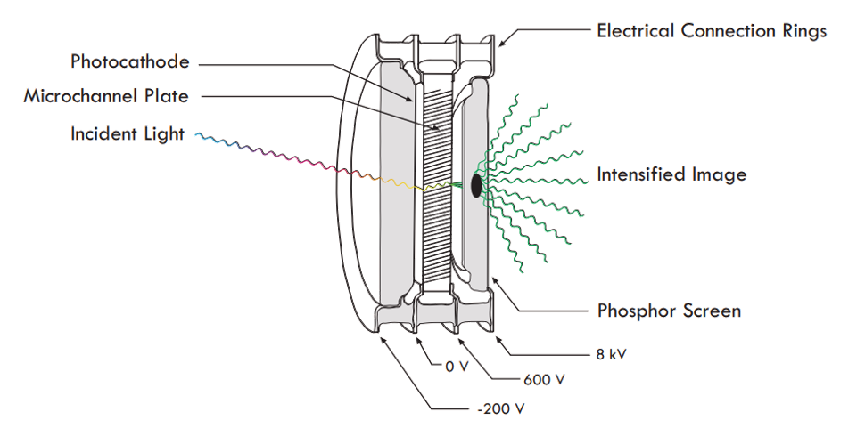
An ICCD camera system’s image intensifier consists of a photocathode, a microchannel plate (MCP), and a phosphor screen. See Figure 7. A fraction (the quantum efficiency, or QE) of the photons incident on the photocathode are converted into electrons. Single photoelectrons are converted into clouds of electrons by the MCP, which acts as a distributed electron multiplier. The electrons released from the MCP then strike the fluorescent screen (phosphor) and cause it to emit far more photons than were incident on the photocathode.2
ICCD cameras and EMCCD cameras each have distinct performance advantages along with inherent limitations. Traditional intensified cameras, the workhorses of ultra-short, time-resolved applications, are limited by non-linearity due to MCP saturation and are less optimal for distinguishing single photons (although it is possible to use them in single-photon counting scenarios). Alternatively, EMCCD cameras, which have become the main tools for ultra-low-light scientific applications, lack ultrashort (i.e., psec to μsec) gating capabilities.2
emICCDs for Ultimate Linearity and Sensitivity
By combining ICCD and EMCCD technologies, Teledyne Princeton Instruments created novel emICCD cameras that are free of the inherent limitations of the two constituent technologies. See Table 1. This emICCD technology delivers both the ultrashort, sub-nanosecond exposure times of ICCD cameras and the on-chip EM gain and high quantum efficiency of back-illuminated EMCCDs
| emICCD | EMCCD | ICCD | emICCD Notes | |
| Linearity | High | High | Medium to Low | Optimized between two gains |
| Gating | Yes | No | Yes | |
| Spurious Noise | Yes, but lower than EMCCD | Yes, but negligible | No | Using lower EM gain |
| Minimum Exposure | Subnanoseconds | Milliseconds | Subnanoseconds | |
| Susceptibility to Bright Light | High | Low | High | |
| Photon-Counting Capability | Excellent (in particular in combination with precise timing down to the nsec range) | Excellent | Fair | |
| System Gain | High | Medium | Low | Two gains available |
Each emICCD camera features an EMCCD fiberoptically bonded to an external image intensifier that utilizes a Gen II (S20/S25) or Gen III (GaAs or GaAsP) photocathode for the highest light throughput. System linearity is superior to that of ICCD cameras. Furthermore, by intelligently leveraging both the intensifier (i.e., MCP) gain and the EM gain, the detector provides a wider dynamic range than that of an intensifier alone. This wider dynamic range is very useful in quantitative measurements for comparing bright and dark scenes within a single image.
Photon Counting with emICCDs
Since emICCD cameras are able to operate at the highest system gain levels by combining intensifier and EM gain, they can easily overcome the excess noise limitations of typical ‘gain’ systems. This capability makes them exceptionally well suited for the detection of single photons (e.g., in single-photon counting experiments).2
Additionally, their impressive gating capabilities make them an excellent choice for single-photon applications that benefit from precise and fast shutter times (e.g., by lowering the number of photons on the detector or by distinguishing events, as in coincidence detection of single photons). The single-photon counting mode in emICCD cameras works essentially the same way as it does in EMCCD cameras, combining the use of high gain with an appropriately selected threshold on the acquired data.
It should be noted that there are ICCD cameras on the market that couple an intensifier to an EMCCD with a lens, as opposed to a fiberoptic bundle. Lens coupling, however, offers lower light throughput and suffers from increased stray light. Coupling via fiberoptics delivers 6x higher light throughput between the image intensifier and the detector than lens-coupled configurations. Fiberoptic bonding also provides a much better signal-to-noise ratio than lens-coupled devices.2
Quantum Research Applications
The first two quantum research examples presented below (i.e., single trapped ion and nitrogen vacancy centers in diamond) utilized state-of-the-art PI-MAX®4 emICCD cameras from Teledyne Princeton Instruments.
Alternatively, imaging applications for quantum research that do not require gating can benefit greatly from advanced high-speed EMCCD technology such as that implemented in Teledyne Princeton Instruments ProEM®-HS cameras.
Example 1: Experimental Scheme To Realize a Nano-Heat Engine with a Single Trapped Ion
Our first example focuses on research conducted jointly by scientists from two universities in Germany (Mainz and Augsburg). This group of scientists proposed an experimental scheme to realize a nano-heat engine with a single ion.4,5
Ion traps enable the manipulation and interrogation of atomic or molecular ions. By using a combination of electric or magnetic fields, charged particles are captured in isolation. Trapped ions can be controlled very well and are excellent quantum memories, providing single-qubit coherence in excess of 10 minutes.
Trapped ions offer an unprecedented degree of preparation and control of their parameters, can be cooled to the ground state, and can be coupled to engineered reservoirs. For these reasons, they have played a prominent role in the experimental study of quantum computation and information processing applications. They are also invaluable tools for the investigation of quantum thermodynamics.4,5
The fundamental question that the aforementioned group of scientists in Germany sought to address was whether or not commonly realized macro-heat engines like those utilized by automobiles, which convert thermal energy into mechanical work, can be scaled down to the single-particle level while retaining the same working principles. The scientists analyzed an experimental scheme for a nano-heat engine using a single laser-cooled ion as working gas.4,5
In experiments performed at the Institut für Quantenphysik, Universität Mainz, the team implemented an Otto cycle, the basis of the four-stroke car engine, by confining the cold ion in a linear Paul trap with a tapered geometry and coupling it to a pair of engineered reservoirs.4,5
In their experiments, a single calcium ion was trapped in the electromagnetic field of a special Paul trap and cooled via laser to a temperature of 1 mK. To drive the ion in a heat engine cycle, the scientists alternately heated and cooled the ion by applying electric noise and laser cooling.4,5
The figure of merit for the experimental demonstration of the single-ion heat engine was the work produced as a function of the temperatures of the heat baths. As the work produced was directly converted into motion in the form of an oscillation at 100 kHz, a precise observation of the latter was crucial.4,5
In order to observe the oscillation of the ion at 100 kHz, the scientists employed an emICCD camera from Teledyne Princeton Instruments. Exposure times of only 0.5 μsec allowed the ultra-high-sensitivity imaging system to resolve the ion motion precisely in both space and time.4,5
The scientists analytically determined the quantum efficiency of the single-ion heat engine at maximum power in various regimes. They also performed Monte Carlo simulations of the engine that not only demonstrated its feasibility but its ability to operate at maximum efficiency of 30% under realistic conditions.4,5
Although micro-heat engines have been constructed employing various types of systems, a quantum heat engine had never been built. Encouraged by their numerical simulations and analysis, however, the scientists went on to fabricate a single-atom engine.6
The fast gating ability of the emICCD camera enabled the group to demonstrate the functionality and performance of the single-ion heat engine, which will lead to a better understanding of the thermodynamics of single particles.4,5
Example 2: Diamond Quantum Dynamics Research
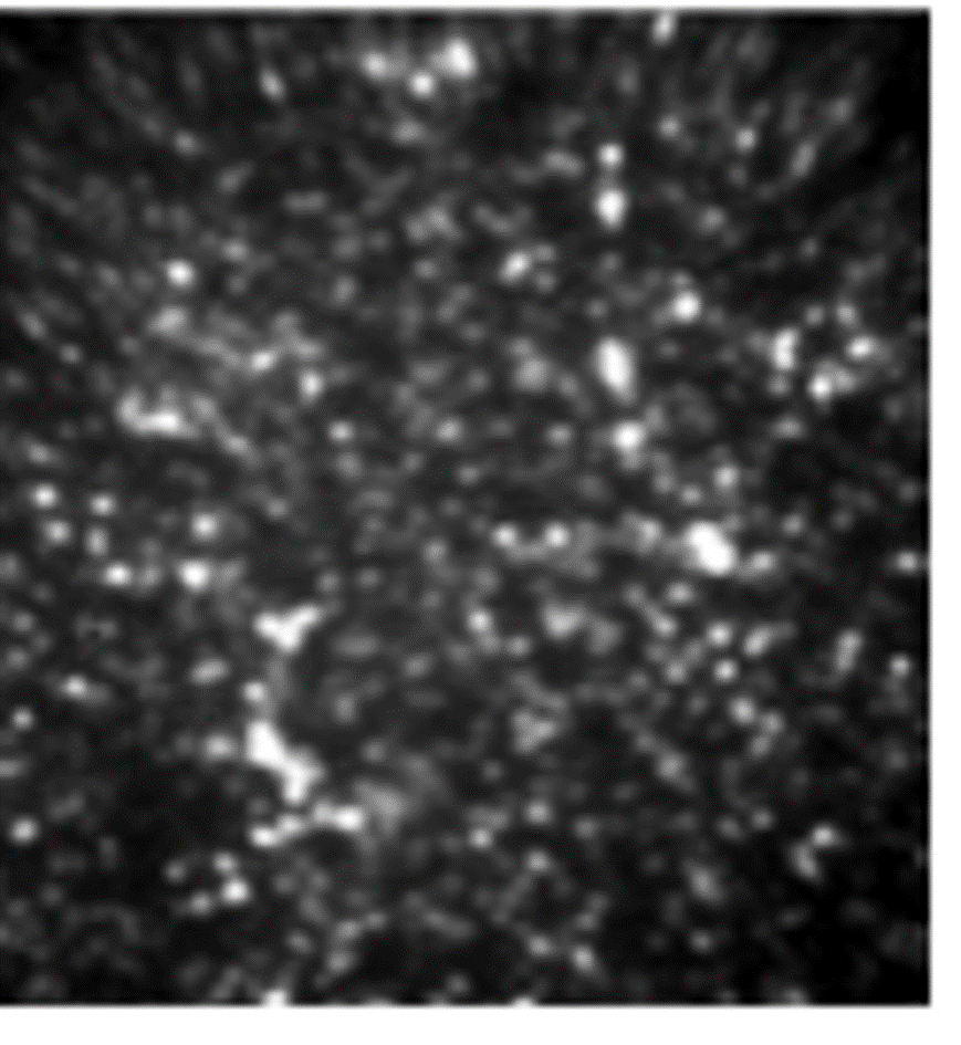
In our second example, researchers at the Université de Sherbrooke in Québec, Canada, led by Ph.D. student David Roy-Guay and supervised by professors Denis Morris and Michel Pioro-Ladrière, employed an ultra-high-sensitivity emICCD camera from Teledyne Princeton Instruments to image the quantum state of NV centers in diamond over a wide surface (100 μm x 100 μm) on a pixel basis.7
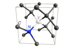
A nitrogen vacancy (NV) center is a defect formed in diamond by one substitutional nitrogen atom and an adjacent vacancy. NV centers have good coherence times (>1 sec) and possess exceptional light-to-spin properties for exploitation in quantum information and entangled photon sources. Applications include quantum computing, medical imaging, and nanoscale sensing.
NV centers can be controlled coherently using electromagnetic fields at room temperature, and NV fluorescence allows simple routes for optical initialization and readout.
Figure 9 shows some of the Canadian team’s data. Synchronization of a microwave generator, an acousto-optical modulator (AOM), and an emICCD camera was achieved by operating the camera in its external trigger mode and counting the number of frames output by “logic out”.7
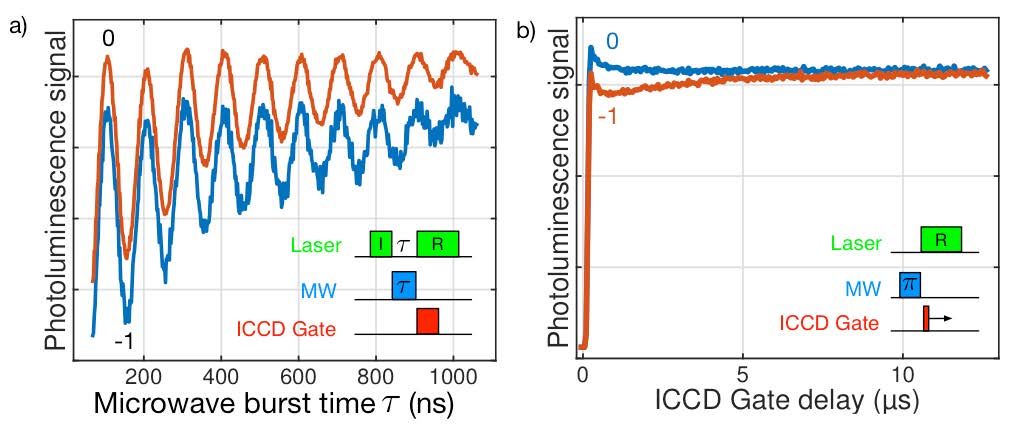
Because of the fast repolarization of the spin state to 0, the gate had to be precisely aligned with the laser readout pulse. This critical alignment was easy to perform via the sequential gating function of the emICCD camera, which moved the gate pulse relative to the trigger pulse. Once the gate pulse was set at the beginning of the readout laser pulse, microwaves were applied with a variable time τ for coherent control of the NV spin state (see inset, Figure 9a). The quantum dynamics of an NV ensemble caught on a single pixel (blue curve, Figure 9a) or averaged over a 10×10 pixel region (red curve) showed excellent signal-to-noise ratio.7
The oscillations showed that the spin state can be flipped from 0 to -1 by applying a 150 nsec pulse, corresponding to a π-pulse. Curve decay was due to relaxation: over 1 μsec, the ensemble of NV centers probed interacted with other spins in the diamond lattice so that their quantum state could no longer be manipulated coherently with high fidelity. Once the π pulse duration had been determined, the spin repolarization dynamics could be measured by preparing the NV in the 0 or -1 state and scanning the gate across the readout pulse (see Figure 9b).7
The maximum photoluminescence contrast between the 0 and 1 state was obtained with a gate width of 1 μsec. Contrary to a ‘boxcar combined with a photomultiplier tube’ detection setup, the fast gating and excellent on/off ratio of the emICCD camera yielded a measurement that was insensitive to the first laser initialization pulse. This guaranteed the maximum visibility for the Rabi oscillations and minimized relaxation and decoherence of the NV centers probed.7
The researchers noted that higher-sensitivity magnetometry can be achieved by applying spin-echo pulse techniques enabled by the emICCD camera’s precision gating features. Such a capability is key to the development of a new scientific tool based on diamond technology, one which will provide unique insights for biology, medicine, chemistry, physics, and geology.7
Scientific InGaAs Cameras
State-of-the-art indium gallium arsenide (InGaAs) cameras deliver exceptional quantitative detection capabilities in the short-wave infrared region of the spectrum. These scientific camera systems extend the vision of quantum researchers well into the near-infrared range, beyond what is possible with silicon-based detectors.
Example 3: Measuring Spectra of Single Quantum Dot Nanocrystals Emitting in SWIR
Our third example involves the use of an InGaAs focal plane array (FPA) camera to study quantum dots. Quantum dots are tiny particles or nanocrystals of a semiconducting material that have diameters ranging from 2 to 10 nm (10 to 50 atoms) and are currently used in medicine, photovoltaics, displays, and biosensing. They possess features that could also be useful in quantum information processing.
Recently, Dr. Han Htoon, a researcher in the Materials Physics and Applications Division of the Center for Integrated Nanotechnologies, Los Alamos National Laboratory, utilized an LN-cooled InGaAs camera from Teledyne Princeton Instruments to perform single-nanocrystal spectroscopy for lead sulfide (PbS) quantum dots emitting at ~1250 nm.8 PbS quantum dots hold excellent potential for applications such as telecommunications, tunable IR lasers, and solar cells.
The image in Figure 10 was acquired using the advanced InGaAs camera coupled to an astigmatism-free imaging spectrograph, also from Teledyne Princeton Instruments.
According to Dr. Htoon, the cryogenically cooled InGaAs camera’s unprecedented long integration times and low dark counts enabled the groundbreaking single-nanocrystal spectral experiments by providing levels of contrast and sensitivity that cannot be achieved with other InGaAs cameras when working with these quantum dots.
Dr. Htoon’s group was the first to report single-nanocrystal spectral studies for this type of quantum dot with emission in the SWIR region. Their work will benefit the understanding and development of SWIR semiconductor nanocrystals for applications ranging from human health to national defense.
A research group at MIT has also used this InGaAs camera to evaluate novel InAs (indium arsenide)-based SWIR quantum dots. The MIT researchers were able to demonstrate that these new SWIR-emitting core/shell quantum dots hold tremendous promise for the next generation of in vivo SWIR imaging.9,10
References
- Princeton Instruments, Inc. (2016). Technical note: on-chip multiplication gain. https://www.princetoninstruments.com/wp-content/uploads/2020/04/TechNote_OnChipGain.pdf
- Princeton Instruments, Inc. (2013). Technical note: emICCD: the ultimate in scientific ICCD technology. https://www.princetoninstruments.com/wp-content/uploads/2020/04/TechNote_emICCD.pdf
- Nobel Media AB (2001). Information for the public. www.nobelprize.org/prizes/physics/2001/popular-information/
- Princeton Instruments, Inc. (2015). Application note: ultra-high-sensitivity emICCD cameras facilitate use of trapped ions for quantum research. https://www.princetoninstruments.com/learn/quantum/emiccd-cameras-facilitate-trapped-ions-for-quantum-research
- Abah et al. (2012). Single-ion heat engine at maximum power. Phys Rev Lett 109, 203006.
- Rossnagel et al. (2014). Nanoscale heat engine beyond the Carnot limit. Phys Rev Lett 112, 030602. 18
- Princeton Instruments, Inc. (2015). Application note: ultra-high-sensitivity emICCD cameras enable diamond quantum dynamics research. https://www.princetoninstruments.com/learn/quantum/sensitive-emiccd-cameras-diamond-quantum-dynamics-research
- Princeton Instruments, Inc. (2018). Case study: measuring spectra of single quantum dot nanocrystals emitting in SWIR. https://www.princetoninstruments.com/applications/customer-research-stories/dr-han-htoon
- Bruns et al. (2017). Next-generation in vivo optical imaging with short-wave infrared quantum dots. Nat Biomed Eng 1, Article no. 0056.
- Princeton Instruments, Inc. (2018). Application note: deep-cooled InGaAs FPA camera enables high-speed, high-resolution in vivo imaging of SWIR-emitting quantum dots. https://www.princetoninstruments.com/learn/swir-nirii/in-vivo-imaging-swir-emitting-quantum-dots
Further Reading
emICCD Cameras for Using Trapped Ions in Quantum Research
Find out how researchers from Germany created a nano-heat engine with only a single ion, and observed it using an emICCD.
emICCD Cameras for Diamond Quantum Dynamics Research
Discover how researchers from Canada used an emICCD camera to image the quantum state of NV centers in diamond.
<500 Picosecond Gating for Atmospheric Pressure Plasma Jets
An application note providing an overview of the experimental setups for atmospheric pressure plasma jets alongside relevant imaging technology.