
In Vivo Raman Spectroscopy
Raman spectroscopy is an important measurement technique in life sciences and biotechnology, from nanoscale experiments analyzing the structure of single biochemical molecules to detection of disease and monitoring properties of tissue. Raman spectroscopists in life science research use excitation and detection in all wavelength ranges from the ultraviolet (UV) to the near (NIR) and short-wave infrared (SWIR) region and selection of the laser excitation wavelength is an important experiment parameter to balance spectral resolution, detection efficiency and avoiding autofluorescence background.
Recently research has seen notable growth for applications of Raman spectroscopy in clinical and in vivo spectroscopy, due to its proven diagnostic potential for monitoring diseases, detection of malignant tissue, calcification of coronary arteries and inflammation. A significant advantage of Raman spectroscopy is speed and the ability to perform label-free measurements. Results are often available in seconds with very high molecular specificity, without special sample preparation or the application of optical labels.
Spontaneous Raman scattering is a weak effect affecting only 1 in 106-108 incident photons, requiring sensitive cameras that are able to detect very low signal levels. Unfortunately, applications on biological tissue often can’t compensate by increasing laser power as tissues could be damaged by high amounts of laser radiation. Therefore, proper selection of a camera for detection of Raman signal is crucial for in vivo Raman measurements.
To find out more about how Raman spectroscopy can benefit life sciences in general, see our page A Brief Overview of Raman Spectroscopy in Life
Sciences
High Sensitivity in the NIR
In vivo Raman measurements on tissues are affected by interference from autofluorescence, which obscures weak Raman signals and complicates measurement analysis. The main tool for mitigating autofluorescence has been the choice of longer (NIR) excitation laser wavelengths, shifting the Raman signal to spectral regions where the influence of autofluorescence background is lower or disappears.
The most commonly used choices for excitation are 785nm or 830nm lasers that also coincide with a window of reduced scattering in tissue to allow for larger optical penetration depths. Since the Raman signals are detected as energy shifts relative to the laser line, the relevant spectral information will be located in the NIR wavelength range.
The challenge for sensitive detection is that the quantum efficiency of Si based detectors are decreasing in the NIR as the detection limit around 1100nm is approached. Moreover, the spontaneous Raman scattering cross section falls off as 1/λ4, reducing signal strength considerably compared with visible excitation. Due to these challenges, proper selection of the detection system is crucial for in vivo Raman spectroscopy applications.
The detector of choice for the NIR wavelength region are deep depleted CCDs, which are back illuminated sensors with increased NIR sensitivity. Their depletion region width is significantly larger than for normal back-illuminated CCDs, increasing their efficiency for red wavelengths that require longer mean free paths for absorption and detection.
Recently super deep depleted cameras (sometimes called HiRho CCDs) have been released with even larger NIR sensitivity. Figure 1 shows how the quantum efficiency of deep depleted “standard” CCD cameras and the super deep depleted high NIR sensitivity cameras compare with increasing wavelength.
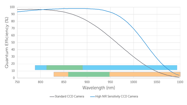
Let’s consider how this efficiency is utilized for Raman spectroscopy experiment for 785nm and 830nm excitation wavelengths, specifically in the spectral band where the Raman signal can be expected. Figure 1 shows two bars, showing the spectral location of the Raman signals for 785nm (blue bar) and 830nm (orange bar) excitation. The important fingerprint region between 500-1500cm-1 is highlighted in green for each case. It corresponds to a wavelength of 817-889nm for 785nm excitation and 865-948nm for 830nm excitation region.
Laser excitation at 830nm is an option when autofluorescence background needs to be reduced further compared to 785nm excitation. However the edge of the high wavenumber region of the signal (2500-3800cm-1) will be partially located at wavelength outside of the detection range of Si CCD detectors (which can’t detect light with wavelengths above 1100nm, corresponding to energy shifts relative to the 830nm laser of > 2900 cm-1 ).
InGaAs detectors can be used for detection in this wavelength range, however at the cost of increasing noise by orders of magnitude. Indeed, for applications with strongest interference from autofluorescence some experiments use even higher excitation wavelengths around 1064nm to further separate the desired signal from the spectral region of the interfering background.
As the signal will be located at IR wavelengths undetectable by Silicon (Si) CCDs, so a deeply cooled InGaAs camera should be used. Deep cooling using liquid nitrogen or advanced thermoelectric cooling are effective at reducing thermal noise and therefore improving the sensitivity of InGaAs cameras.
It is evident from Figure 1 that standard deep depleted cameras as well as increased NIR sensitivity cameras are well suited to detect the fingerprint region of the Raman signal with high efficiency. However, the latter provide better high sensitivity coverage for all relevant regions of the Raman spectrum.
Low Noise and Deep Cooling
Weak signals require the spectroscopic camera to operate at low noise levels, requiring particularly low readout and dark noise. Well-engineered camera electronics will keep readout noise at a minimum level. Dark noise is generated by thermally generated charge in each pixel in addition to charges created by incoming light on the sensor. Dark noise also introduces a bias into the signal which increases with longer exposure time, adding additional noise to the signal.
Spectroscopy cameras are often operated by vertical binning of detector rows. Binning collects charges for every pixel in a column (i.e. all charges corresponding to the same wavelength) in the serial register before readout (so readout noise is only accumulated once). However, during binning the dark charge from every pixel in the column also accumulates. As it is common to bin dozens or even hundreds of detector rows, the effective accumulation of dark charge can be orders of magnitude larger than values from camera datasheets (that are specified on a per pixel basis). A sensitive camera for in vivo Raman spectroscopy should therefore be able to operate at very low temperatures to avoid dark current building up on the sensor.
For in vivo applications thermoelectric cooling is used most often, to avoid handling of cryogenic liquids. The latest generation of deep, thermoelectric cooled cameras can reach temperatures from -75°C to -95°C without requiring any external equipment (for example liquid coolant circulation or chillers).
Alongside the thermoelectric cooling design, a good vacuum of the sensor chamber in the camera is very important to achieve low temperatures. The vacuum should be maintenance free in operation and have a long lifetime, ideally over the lifetime of the camera.
Low Fixed Pattern Noise and Anti-Fringing Technology
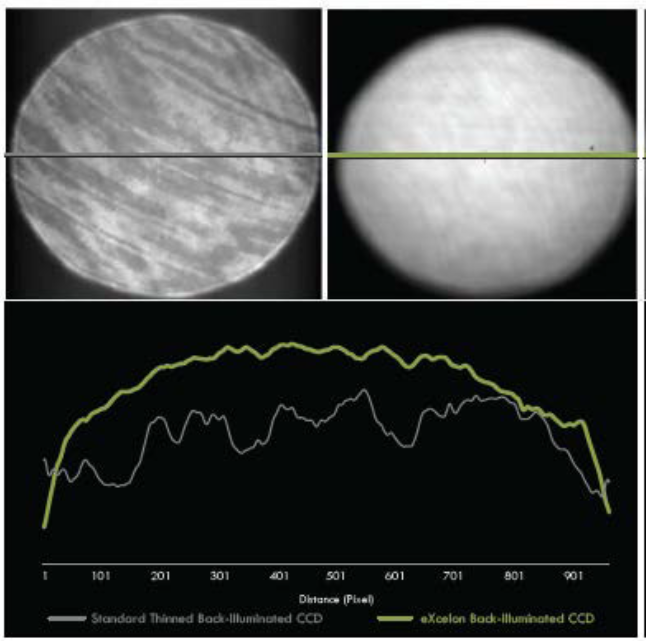
Etaloning is caused by interference of light in the sensor. It occurs in back-illuminated CCD cameras when the wavelength detected is greater than 700nm, as the detector material (silicon) becomes more transparent towards the detection limit at 1100nm. Etaloning will appear as a series of interference fringes across the sensor visible on both images and spectra.
For in vivo Raman spectroscopy these etaloning effects further complicate background subtraction and data analysis of the complex spectra that are shown by biological systems. Ideal detectors for in vivo Raman spectroscopy need to reduce or eliminate these effects.
Sensor enhancements addressing these shortcomings of CCD camera sensors have been deployed to great effect, as they can be applied not only to eliminate etaloning, but also to broaden and increase the spectral sensitivity of the sensor.
For example, Teledyne Princeton Instruments eXcelon process has been designed to eliminate etaloning (see Figure 2) and create an ultra broadband high sensitivity CCD camera. It significantly improves the quantum efficiency by up to 40% with QE >90% from the UV to the visible. eXcelon was also designed to give researchers a higher performance option compared to single or 2-layer AR coatings that are sometimes employed.
Based on the success of eXcelon technology, a new CCD enhancement process called eXcelon 4 has been developed specifically for NIR Raman applications, and more specifically in vivo Raman spectroscopy. eXcelon 4 provides the best suppression of etaloning effects for Raman measurements excited with 785nm and 830nm lasers, from the low wavenumber and fingerprint regions to the high wavenumber regions.
Detector Size
In vivo Raman measurements often use fiber optic probes with bundles of fibers in a round to linear configuration. This arrangement places the fiber ends in a dense packed arrangement on the signal collection side and distributed along the spectrograph entrance slit on the spectrograph/detector side (see Figure 3).
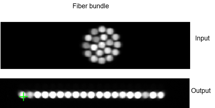
This configuration increases signal collection by the fibers covering a large area and optimizes coupling efficiency into the spectrograph while high spectral resolution can be maintained for measurements. (see our Technote: Improving the collection efficiency of Raman scattering)
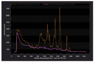
Figure 4 shows the dispersed image of an atomic emission lamp spectrum sampled through a such a fiber optic bundle. The linear arrangement of the fibers in the vertical direction is clearly visible.
Different areas of the fiber bundle might also have different spectroscopic functions. For example, spatially offset Raman spectroscopy (SORS) uses the spatial arrangement of fibers on the tissue side to obtain depth dependent data from subsurface tissue regions.
Optimal detectors for in vivo Raman spectroscopy will have large enough width and height to cover a wide spectral range at sufficient resolution and fiber bundles that accommodate a large number of fibers. Spectroscopy CCDs such as the Teledyne Princeton Instruments BLAZE and PIXIS camera series have tall sensor options with 27mm width and 8mm height, providing have sufficient size to include dozens of fiber optic traces at high spectral resolution. It should be noted that such a detector should be paired with a spectrograph with low aberrations (e.g. astigmatism) across the entire focal plane. Otherwise spectral quality and resolution will be reduced due to the introduction of aberrations.

Summary
Raman spectroscopy for in vivo diagnostic measurements has to deal with challenges of weak signals and large fluorescent background radiation. Deep depleted and HiRho CCD cameras are the optimal detector for this application due to their high sensitivity in the NIR. The latest generation of cameras are optimized for in vivo measurements, with the addition of specialized hardware components such as:
- Advanced thermoelectric cooling systems to reach temperatures as low as -95°C without need for chillers or liquid coolants
- Sensor enhancements to eliminate etaloning and fringing in spectral data
- Large sensors to help maximize signal collection with high spectral resolution
References
- Technote: Novel, performance-enhancing CCD technology
- Technote: Improving the collection efficiency of Raman scattering
Further Reading
Raman Spectroscopy in Life Sciences
Brief overview of how Raman spectroscopy is advantageous for life science applications, such as characterizing biomolecules and for biosensing.
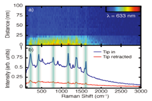
Tip-Enhanced Raman Spectroscopy
Article describing the fundamentals of tip-enhanced Raman spectroscopy and the investigations of researchers from the University of Colorado at Boulder.
Related Raman Products
Raman spectroscopy can be implemented in various ways dependent on the sample being studied. Therefore it is important to use the correct equipment. Find out more about your options here.